RF Over Fibre (RFoF) real time applications: Part 3 – RF as a Service (RFaaS)
Author: Andy Haslam, Director of Business Development, PPM Systems
PPM System’s RFaaS is the implementation of an RFoF based EW System, where the RF signals between antennas and signal generators / receivers are converted into the optical domain for distribution as RFoF. The lossless nature of the fibre optic cabling enables antennas to be placed in optimised positions for performance, and the hub / star network topology of the optical distribution enables any antenna feed to be routed to any signal receiver (and vice versa for signal generators). The any-to-any mapping of antennas to signal receivers / generators means that RF signals can be distributed to and from any equipment in any ship compartment with an fibre optic feed i.e., providing RF signals on request or – RFaaS
PPM Systems’ RFoF Data Distribution System Provides:
- Dynamic Configuration. Gives optical routing functionality for dynamic configuration to optimise the OC / EMSO application to the operational environment and the platform
Step Change in Performance. Eliminates the performance limitations of extant coaxial point-to-point data links to maximise the effectiveness of platform CEMA / EMSO capabilities - Embedded Future Growth. Includes inherent future growth with the ability .to rapidly up-scale the solution using its modular architecture, and to simultaneously support RFoF, RFoIP and the distribution of digital Command and Control (C2) data if required
Secure Room Independence
In ES applications, there can often be multiple users of the same antenna feeds for different types of ES activity in different locations. In these instances, the RFaaS solution can provide a separate set of feeds for each Secure Room (where signal receivers are located) such that any antenna to receiver routing in one Secure Room is completely independent of, and does not affect other Secure Rooms.

What does an RFaaS Solution Look Like?
PPM Systems’ RFaaS has 3 logical elements: Antenna suite, Distribution Room and Receiver Room(s); this is illustrated in Figure 1 below using a RFaaS solution for an ES system as an example, along with the primary functions of each logical element, and is further described below:
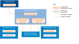
- Antenna Suite All antennas are optically enabled by converting the RF feeds from each into the optical domain via Electro-Optic (EO) converters. All RF feeds from all antennas are converted into separate optical feeds such that these feeds can be appropriately routed in the different compartments. The antenna suite consists of the platform’s ES antennas, regardless of the end user / secure room, with these feeds then are converted into the optical domain using a variant of PPM’s proven Close Coupled Unit (CCU). The CCU is typically mounted directly to the bottom of each antenna to minimise any signal losses that are prevalent at higher frequencies in coaxial cabling.
- Distribution Room The distribution room splits the optical feeds from all antennas, presenting an optical feed for each antenna ready for transportation to any receiver room. This transportation is via a ruggedised multi-core fibre optic cable per receiver room (i.e. a separate cable for each), where each optical feed has a separate fibre within the fibre cable (hence a multi-core cable).
- Receiver Room(s) The optical switching, combining and splitting functionality is implemented once the antenna feeds are split by each receiver room, such that the routing of the antenna feeds to receiver equipment ports is only applied to the desired compartment, such that the routing of the antenna feeds to receiver equipment ports is only applied to the desired room. For example, an operator can dynamically reconfigure the routing of antenna feeds to receiver equipment ports to best suit the operational circumstances, without having any impact of the other compartments’ antenna feeds.